Quantum QR-Code Generator
Contents
Abstract
Nowadays we all use QR code for multiple purposes like making payments, sharing WiFi, etc. Have you ever wished to generate such QR code on your own ?, this project is for generating a QR code using Qiskit Sdk and Python programming language.
Project Contribution
This project work was submitted to the QC-Hack 2021 organized by QuantumCoalition. During the hackathon, I had the opportunity to learn and implement ideas in the field of Quantum Algorithms. It was a pleasure to be part of this hackathon. Thanks to IBM Quantum & Google Quantum AI, I received credits to execute our code on real quantum hardware. Access the event certificate.
About QR Code Generator Project
QR Code is a machine-readable matrix barcode that uniquely represents information. With the increase in optical capabilities of smartphones, the use of QR codes started increasing. In this project, we build a QR Code generator using Qauntum algorithm based Modules.
Generate QR Code in Python
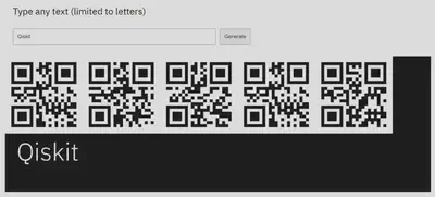
The above demo creates an image with a quantum computer. Even better, the image is a word written by a quantum computer. Each line shows the amplitude of the binary representation of a letter of as an output of the Bernstein-Vazirani algorithm.
Then it generates the QR code from the above inputs and save in the given location using the qrcode module. A QR code can be generated by typing in the box below, but instead of using pulsar data, it uses data from a quantum computer.
General Implementation
A step-by-step explanation of the code along with the packages used and their purpose:
The first package used is
qiskit, which is a software development kit for building quantum programs. It provides a collection of tools, algorithms, and software components that enable the creation and execution of quantum circuits on a variety of backends.The next package used is
qrcode, which is a Python library that generates QR codes. It allows you to create QR codes for a wide range of use cases, such as encoding URLs, text messages, phone numbers, and more.The third package used is
plot_histogramfromqiskit.visualization, which is a module in the qiskit library that provides tools for visualizing quantum circuits and their results.Import the qiskit library, which is needed to define quantum registers and circuits, and to execute them on various backends.
Import qiskit again but gives it an alias of
qk, which is a common shorthand used by many developers.Import
qrcode, which is used to generate a QR code for the encoded message.Import the
plot_histogramfunction fromqiskit.visualization, which is used to plot the histogram of the measurement outcomes.The user enters a message to encode and stores it in the variable message.
Remove duplicate characters from the message by converting it to a set, sorting it, and then joining it back together as a string. This is done to ensure that the message is unique and has a consistent order.
Convert the message to binary by using the format function to convert each character to its 8-bit
ASCIIcode and then concatenating the results.Initializes the quantum circuit by creating a quantum register q with a size equal to the length of the binary message plus one, and a classical register c with a size equal to the length of the binary message. It then creates a quantum circuit qc with these registers.
Apply a Hadamard gate
H gateto all the qubits in the quantum circuit qc. This creates a superposition of all possible states for the qubits.Define the
oracleas a secret binary string, which is used to mark the state that we want to find. In this case, the secret binary string is the complement of the binary message, where each 0 is replaced with 1 and each 1 is replaced with 0.Apply a
Z gateto each qubit in the quantum circuit qc that corresponds to a 1 in the oracle. This flips the phase of the state|x>for each marked element, where|x>is the binary representation of the element.Apply the Hadamard gate
H gateto each qubit in the quantum circuit. This puts the qubits in a superposition of all possible states, which will allow us to measure all possible outcomes with equal probability.Add a measurement gate to each qubit in the quantum circuit. This collapses the superposition of states into a single classical bit.
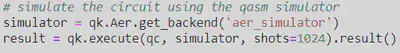
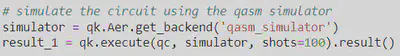
Finally, the quantum circuit on a quantum simulator using the
Aerpackage from Qiskit.
The Aer package provides a range of simulators for running quantum circuits. In this case, we use the qasm_simulator backend, which simulates the behavior of a real quantum computer and returns the outcomes of the measurements in the form of a dictionary containing the counts of each possible result.
The execute function takes the quantum circuit qc and the backend as inputs, and runs the circuit on the backend to obtain the results. The shots parameter specifies the number of times the circuit should be run to obtain statistics on the outcomes.
The result variable contains the result of the simulation, which includes the counts of each possible outcome. The counts variable is then used to print the result of the algorithm, which is the binary representation of the marked element.
Project Summary
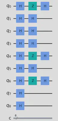
The user inputs a message u as shown below to encode which is then converted into binary format. The code then initializes a quantum circuit with a quantum register consisting of the length of the binary message plus 1 and a classical register with the length of the binary message.

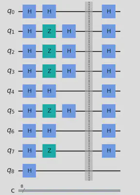
The Hadamard gate H gate is applied to all the qubits in the quantum register, and a secret binary string (oracle) is defined. The Z gate is applied to the qubits that correspond to 1 in the oracle.
The H gate is applied to all qubits except the last one. The qubits are then measured and the result is stored in the classical register.
The above circuit is simulated using the aer_simulator as shown below and the result is extracted and converted to binary. The QR code is generated using the qrcode library and saved as an .png image.
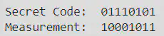
Finally, the secret binary message and the binary measurement are printed as shown below. In this specific run of the code, the input message was u, the secret code was 01110101, and the measurement was 10001011.
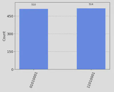
And the histogram of the result is plotted as shown below.
How exactly is qrcode generated using a quantum computer in this project ?
The message is encoded into a quantum state using quantum gates, and the measurement results are then used to generate the QR code using the classical library qrcode.
In more detail, the quantum circuit is designed to encode the binary message into a superposition of quantum states, and then use the measurement results to extract the encoded message. The H gate is applied to all qubits to put them in a superposition of states. The Z gate is applied to the qubits corresponding to 1 in the oracle to flip the phase of those states. Finally, the H gate is applied to all qubits except the last one to encode the message.
The qubits are then measured, and the measurement results are used to extract the encoded message in binary format. The extracted message is then passed to the qrcode library to generate the QR code.
Therefore, the quantum circuit is used to encode the message into a quantum state, and the classical code is used to extract and use the information from the quantum state to generate the QR code as shown below.

The code uses the Bernstein-Vazirani algorithm as a subroutine to encode the message into a quantum state.
Verified the obtained QR-code with the Google_lens:

In the Bernstein-Vazirani algorithm, a secret binary string (oracle) is encoded into a quantum state, and the algorithm’s goal is to determine the secret binary string using the quantum state’s measurement results. The oracle string is used to generate the quantum state by flipping the phase of the qubits corresponding to 1 in the oracle string.
In this model, the secret binary string is generated from the user’s input message by converting it to binary and flipping the bits to create an oracle string. This oracle string is then used to encode the message into a quantum state using the Z gate to flip the phase of the qubits corresponding to 1 in the oracle string. This encoding process is equivalent to the encoding process in the Bernstein-Vazirani algorithm.
Adding Error Correction code
According to the results obtained, the secret code for the message u is 01110001, and the measurement obtained from the quantum circuit is 01111001. These two binary strings should be equal for the encoding and decoding to be successful, and in this case they are different. This is expected, since errors can occur during the encoding process due to the noisy nature of quantum devices.
The AerSimulator in Qiskit also allows you to simulate noise in your quantum circuits. Specifically, you can add noise models to the simulator to simulate various types of errors, including:
- Depolarizing error
- Amplitude damping error
- Phase damping error
- Thermal relaxation error
- Bit-flip error
- Phase-flip error
- Readout error
In order to mitigate error, an error correction step is added to the quantum circuit in case the measurement does not match the secret binary string. Specifically, it uses an ancilla qubit to flip the last qubit of the quantum register if necessary, effectively correcting the error.
The above image shows the improvised circuit with added correction steps.

The correction steps was icluded as shown in the above code-snippet.
The above circuit was simulated using the qasm_simulator as shown above.
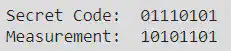
The secret binary message and the binary measurement are printed as shown below. For the input message u, the secret code was 01110101, and but the measurement obtained were improvised, even though not accurate. It was 10101101.
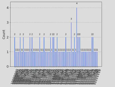
The histogram of the result is plotted as shown above.
Using Quantum Fourier Transform (QFT), to support larger messages
The previous implementation is limited to encoding messages of length 1-2 characters. Hence, to make the project more practical, I have extend the encoding process to support larger messages. One possible approach is to use the Quantum Fourier Transform QFT to encode the message into a quantum state, similar to how the QFT is used in Shor’s algorithm.
In this modified code, I first calculate the required number of qubits based on the length of the binary message, and then apply the QFT to the qubits. The oracle is applied by flipping the qubits corresponding to a 1 in the binary message. Finally, the inverse QFT is applied to the qubits, and the measurement is performed on all qubits except the last one. The resulting binary measurement is used to generate the QR code. Note that the QFT is applied in a similar way to how it is used in Shor’s algorithm to factor integers.
The number of letters that can be encoded using QFT-based encoding depends on the number of qubits available in the quantum computer. Each qubit can represent two values, 0 or 1, so the number of possible states that can be encoded using n qubits is 2^n.
For example, if you have 5 qubits, you can encode 2^5 = 32 different states, which can represent a larger number of characters than the approach used in the original code. However, it is important to note that the number of qubits needed to encode a message grows exponentially with the length of the message, making it challenging to encode longer messages on current quantum computers.
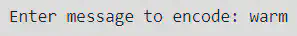
Unlike earlier, this time the user inputs a message warm as shown above to encode which is then converted into binary format.
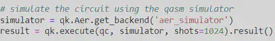
The above circuit is simulated using the qasm_simulator as shown above.
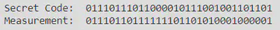
For the the secret binary message warm, the secret code and it’s binary measurement are printed as shown above.
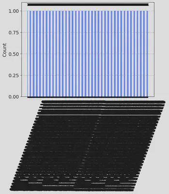
Rhe respective histogram of the result is plotted as shown above.

And the respective QR code generated through quantum state is shown above .
Verified the obtained QR-code with the Google_lens:

Why only 7 bits instead of 8 to represent a letter ?
The fewer bits used, the more accurate the result. When converting from text to binary in Python, the data is prepended with 0b, which is just a computational way of saying “binary is about to follow”. In my script I scrape both of these off. If you were to google an Ascii to binary table, you would see all text starts with 0. Again, we don’t need that, so I scrape it off. Like the above explanation about how circuit depth effects accuracy, so does the number of qubits used, called circuit width. Both circuit width and depth to account for accuracy are taken into consideration, called quantum volume (or QV). For this interactive implementation, I ran all circuits on the quantum computer call ibmq_16_melborne with the highest quantum volume, with QV64.
Future Scopes and Improvements
Error Correction: One potential issue with the current implementation is that the QR code may be susceptible to errors due to the inherent noise in quantum systems. To address this issue, we can use quantum error correction codes to protect the encoded message against errors. This would require a deeper understanding of quantum error correction and how to implement it in the circuit.
Hybrid Approach: Another approach to enhance the project is to use a hybrid classical-quantum approach, where the encoding process is performed on a classical computer, and the decoding process is performed on a quantum computer. This approach can potentially improve the efficiency of the overall process while leveraging the strengths of both classical and quantum computing.
Security: While the current implementation uses the Bernstein-Vazirani algorithm to encode the message, it is not inherently more secure than a classical QR code. To increase the security of the encoded message, we can explore other quantum cryptographic protocols, such as Quantum Key Distribution
QKD, that leverage the properties of quantum mechanics to ensure secure communication.Generalization: Finally, we can generalize the project to support other types of codes beyond QR codes, such as barcodes or other types of two-dimensional codes. This would require a deeper understanding of the structure and encoding schemes of other types of codes and how to implement them in a quantum circuit.
Shisheer S Kaushik
Quantum Technology enthusiast